

With high-performance 2.4 GHz RF, low current consumption,an AI/ML hardware accelerator Secure Vault
Understanding Slew Rate in Op-Amp and How to Measure and Calculate it for your Designs

An ideal op-amp is a voltage amplifier with infinite input impedance, zero output impedance, and infinite bandwidth. In the real world, however, these parameters are limited by small imperfections in semiconductor manufacturing, effects of temperature, and so on.
There is one parameter that is much overlooked but stands out in the above regard, and that is the slew rate. It is not a parasitic effect, rather a deliberate slowing down of the op-amp to ensure stability.
In this article, we will learn about theslew rate of an operational amplifier, where it comes from, and we will also do some calculations for the classic741 op-amp.
Slew Rate – Definition
Themeaning of Slew ratebasically refers to how fast the op-amp is capable of changing its output voltage in response to a change in input.
Slew rate is usually measured in units of a volt per unit time, more commonly in volts per microsecond, or V/µs. An ideal op-amp has an infinite slew rate, meaning it can change its output instantly with any change in input.
The diagram given below shows the output of an op-amp in response to a step input.
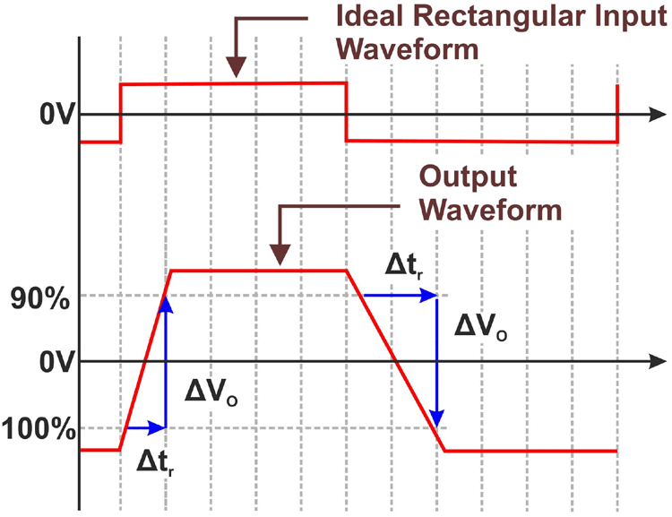
The diagram clearly shows that the op-amp has a finite rise time, where the voltage increases linearly with time. This slope of the output voltage with respect to time is the slew rate.
Why do we have Slew Rate in Op-amps?
The output swing is deliberately limited in op-amps to ensure stability through the use of a compensation capacitor, which limits the output slew rate.
The figure given below shows the effects of having a compensated and uncompensated op-amp.
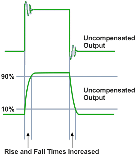
Although uncompensated op-amps are faster, because of the fast-rising and falling edges, there is ringing present and this can lead to stability issues.
Compensation is implemented by adding aMiller capacitorto the driver stage of the op-amp.
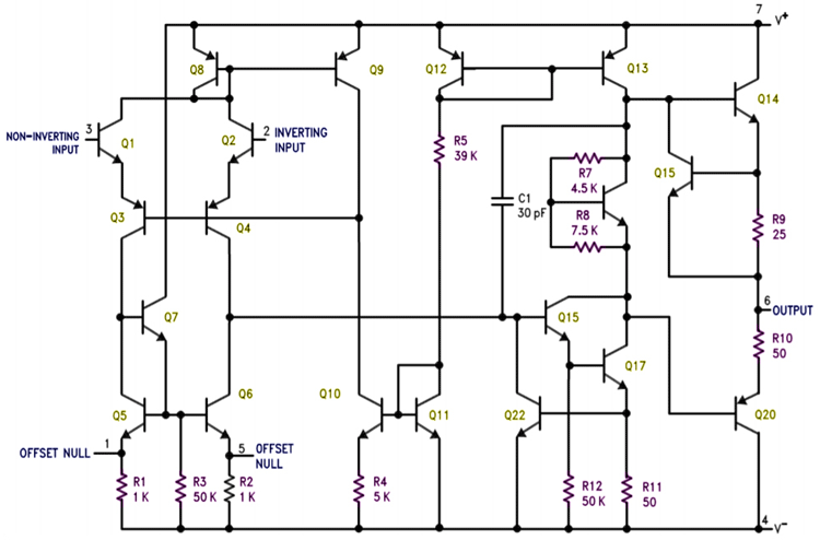
In the above figure, the compensation capacitor is C1, with a small value of 30pF. It is placed between the input and output of the output transistor driver. This can be simplified to the below figure.
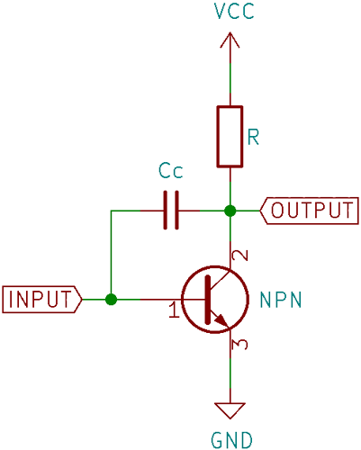
Here, a capacitor is added between base and collector. This capacitor is sometimes referred to as a Miller capacitor because it is similar to the parasitic Miller capacitance between the base and collector of a BJT transistor.
As the input rises, the output on the collector begins to fall. This creates a voltage difference across the capacitor, and a current begins to flow through it.
Following the simple formula that relates voltage, current, capacitance, and time for a capacitor:
I/C = dV/dt
We can understand that the voltage across the capacitor increases in a linear fashion. This voltage is seen across the output and looks like a ramp waveform. This prevents the output from changing abruptly when the input changes and the output slew rate is determined by the capacitance of the compensation capacitor and the driving current. This basic principle is used to compensate almost all op-amps.
为什么运算放大器转换速率有限?
The most important reason as to why op-amps are slew-rate limited is stability. Amplifiers with a high enough gain at a frequency when the output phase shift is above 180 degrees can oscillate.
A high slew rate means that the signal contains high-frequency components, which can lead to problems. A compensation capacitor low-pass filters these high-frequency components, and as a result the output slew rate decreases.
How to Calculate Slew-rate of an Op-Amp?
There are two ways one can follow formeasurement for Slew Rate. The first is to measure the output swing using an oscilloscope and using the followingSlew Rate Formulato calculate slew rate:
Slew Rate = (Vi– Vf)/(ti– tf)
Where Viis the initial voltage, Vfis the final voltage, tiis the time when the initial voltage is measured, and tfis the time when the final voltage is measured. Theunit of slew rateis always given in volts per microsecond. This method is easily done using an oscilloscope and cursors.
Now, if we apply the same formulae for an ideal op-amp, the time delay (ti– tf) will be zero and hence the slew rate will be infinity. So, in theory, theslew rate of the ideal op-ampwill always be infinity.
通常,初始电压被10%的the maximum value and the final voltage is 90% of the maximum value since this is the common range which is measured as rise time. The slew rate value is always given in the datasheet of the respective op-amp.
Slew Rate of IC 741 Op-Amp – Example Calculation
The LM741 is a classic op-amp that has been around for a very long time and is the perfect specimen for this example. In every op-amp datasheet, one can find a plot of the large-signal output response.
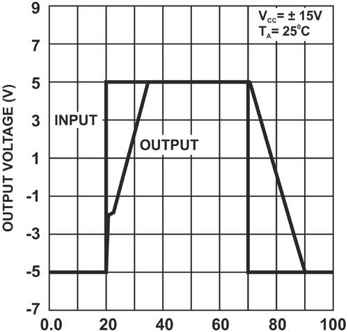
In this plot, it is clearly seen that the output voltage slews with a fixed slope.
Taking the falling edge, which starts at 70µs and ends at 90µs, which makes for a time difference of 20µs, and the voltage swing, which is 10V (from -5V to +5V) and using the above formula, we get a slew rate of 0.5V/µs, which corresponds perfectly with the value stated in the datasheet.
Slew rate was defined, the cause of and the reason for slew rate was explained, and an example calculation for the LM741 op-amp was carried out.


